This information is taken from the S14 factory Service Manual
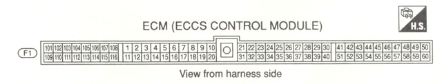
| Pin | Connection | Pin | Connection |
| 1 | Spark #1 (to power transistor) | 11 | Spark #3 (to power transistor) |
| 2 | Spark #2 (to power transistor) | 12 | Spark #4 (to power transistor) |
| 3 | 13 | ||
| 4 | IACV-AAC Valve Output | 14 | Auto Trans Interface DT2 (to pin 11) |
| 5 | Auto Trans Interface DT1 (to Pin 10) | 15 | Auto Trans Interface DT3 (to pin 12) |
| 6 | 16 | ECCS Relay Ground | |
| 7 | Tachometer | 17 | |
| 8 | 18 | Fuel Pump Relay Ground | |
| 9 | A/C Cutout Relay Ground | 19 | Cooling Fan Relay 1 (low speed?) |
| 10 | Power Transistor Ground (20, 107, 108, 116) | 20 | Power Transistor Ground (10, 107, 108, 116) |
| 21 | CONSULT Data In | 31 | CONSULT Data Clock |
| 22 | CONSULT Data Out | 32 | Check Engine Lamp |
| 23 | Knock Sensor | 33 | Cooling Fan Relay 2 (high speed?) |
| 24 | 34 | Power Steering Switch | |
| 25 | Wastegate Solenoid Ground | 35 | Boost pressure signal |
| 26 | MAF Signal | 36 | |
| 27 | MAF Signal | 37 | |
| 28 | Water Temp Sensor | 38 | TPS Signal |
| 29 | Oxygen Sensor Power | 39 | |
| 30 | Boost, TPS, Water Temp Sensor Ground | 40 | |
| 41 | CPS REF Signal (Tied to 51) | 51 | CPS REF Signal (Tied to 41) |
| 42 | CPS POS Signal (Tied to 52) | 52 | CPS POS Signal (Tied to 42) |
| 43 | Start Signal (from Ignition Switch) | 53 | Speed Sensor |
| 44 | Neutral Switch | 54 | Rear Window Heater Signal (Load) |
| 45 | Ignition Switch (ON) | 55 | |
| 46 | Air Conditioning Switch Output | 56 | TPS Automatic Trans Interface (to pin 34) |
| 47 | CONSULT Connector Check In | 57 | |
| 48 | TPS, Boost Pressure Power Supply | 58 | Permanent power (tied to 109) |
| 49 | ECCS Power (tied to 59) from ECCS Relay | 59 | ECCS Power (tied to 49) from ECCS Relay |
| 50 | Ground | 60 | Ground |
| 101 | Injector #1 | 109 | Permanent power (tied to 58) |
| 102 | EGR control valve | 110 | Injector #2 |
| 103 | Injector #3 | 111 | |
| 104 | 112 | Injector #4 | |
| 105 | 113 | Valve Timing Solenoid Ground | |
| 106 | 114 | ||
| 107 | Power Transistor Ground (10, 20, 108, 116) | 115 | Oxygen Sensor Signal |
| 108 | Power Transistor Ground (10, 20, 107, 116) | 116 | Power Transistor Ground (10, 20, 107, 108) |
If you want the basic ECCS wiring, click here. Be warned, this is 545KB JPEG file